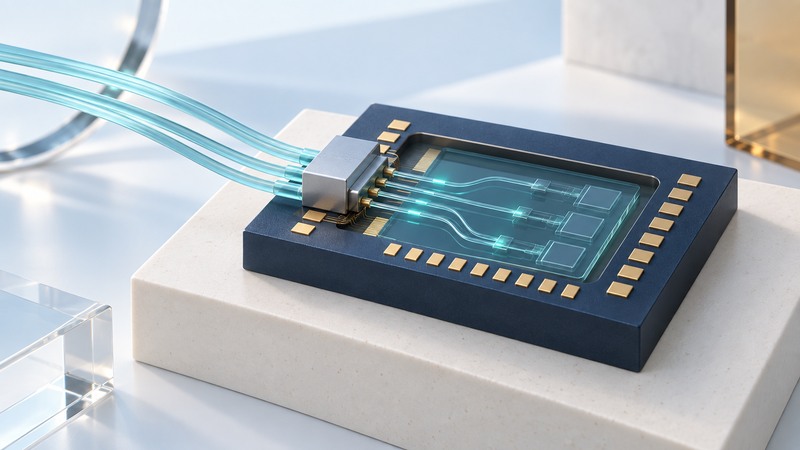
Silicon photonics puts optical functions such as guiding, modulation and detection into a chip-scale platform built around silicon processing. The useful engineering question is how those functions connect to the light source, electronics, package and fiber. Follow the entire signal path before comparing a headline bandwidth or energy figure.
This guide introduces that path for readers familiar with basic electronic signals. It complements module-selection guidance by looking inside the optical engine and at the interfaces that make integration practical.
Follow one direction of communication
On a narrow screen, scroll the table horizontally. Keyboard users can focus the table region and use the arrow keys.
| Function | Role | Question for the design |
|---|---|---|
| Light source | Supplies the optical carrier. | Where is the laser, how is it coupled, and what power reaches the modulator? |
| Driver and modulator | Encode an electrical signal onto light. | What drive, bandwidth, extinction and insertion loss are required? |
| Waveguide and routing | Guide light between functions. | Which wavelengths, bends, crossings and losses belong to the path? |
| Coupler and package | Connect chip-scale optical modes to a fiber or another optical component. | What alignment, polarization, reflection and thermal constraints apply? |
| Photodetector and receiver electronics | Convert received light into an electrical signal and recover data. | What sensitivity, overload, bandwidth and error performance are required? |
A photonic platform can contain several materials and fabrication steps. The phrase “silicon photonics” describes a technology family, not a promise that every active function is made from pure silicon or fabricated in one identical process. Identify the material and integration method where it affects the operating limits.
Locate the boundaries hidden by “integrated”
Integration can occur on a die, across bonded dies, in a package or between neighboring packages. Electronics such as drivers and transimpedance amplifiers also need electrical connections, power and heat removal. Moving an optical engine closer to a processor changes both electrical reach and packaging/service requirements.
A useful concrete example is imec and Ghent University’s June 2025 microwave-photonics demonstration. It combined silicon-platform optical functions with an indium-phosphide optical amplifier added by microtransfer printing. The research demonstrates a particular integration approach; it does not establish that every silicon-photonics product has that architecture.
When reading a product or research claim, draw boxes around what is included. Mark the light source, electrical drivers, control loops, fiber connection and receiver. This immediately exposes differences between a chip measurement and an operating system.
Keep optical loss referenced to actual points
A commercial receiver sensitivity may instead be specified at the module’s external connector. If so, do not subtract internal coupling loss again when using that specification. Match wavelength, modulation, data rate, correction assumptions and error criterion as well as the physical reference plane.
For installation-level minimum and maximum power checks, use the pluggable-transceiver guide.
Treat alignment and temperature as functional requirements
imec’s discussion of high-density optical interfaces explains why coupling geometry, alignment tolerance and redistribution of optical paths matter for packaging. A low-loss laboratory connection can be difficult to reproduce economically across many assembled units.
- Coupling: record the supported fiber, alignment tolerance, attachment process and interface loss.
- Thermal behavior: establish how wavelength-sensitive functions remain usable across temperature and power changes.
- Electrical interface: define driver and receiver connections, control requirements and test access.
- Manufacturing: plan screening before expensive assembly and tests after packaging.
- Service: identify replaceable elements, connector handling and what happens when a light source or optical engine fails.
Temperature-control circuitry can contribute to the power budget. Include it when evaluating energy per bit, along with the source and the necessary electronics. Always state whether a published figure describes one component, a lane, an optical engine or an end-to-end link.
Read a demonstration as a defined result
imec’s wafer-level testing article describes screening active and passive photonic functions before committing further packaging cost. That is a useful distinction when assessing evidence: a good component result and a high-yield packaged system answer different questions.
- Identify the actual measured hardware, material platform and integration level.
- Write down rate per lane, lane/wavelength count and what the reported total includes.
- Record loss, power, temperature and error-measurement conditions.
- Separate demonstrated values from projections, design targets and product qualifications.
- Ask for packaged-unit variation, reliability, test coverage and supply support where the decision involves production.
A clear comparison can end with an unresolved requirement. For example, one approach may meet the optical budget while leaving a packaging tolerance or service strategy unproven. Record that gap explicitly so the next measurement answers a real decision.
Keep a working record
Download the silicon photonics worksheet (editable text). Save a copy for each comparison or test. It includes the example assumptions, fields for source references and space for your results.