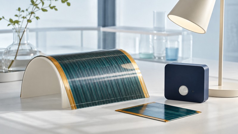
Organic photovoltaic cells use carbon-rich semiconductor materials to convert light into electricity. Their material and manufacturing choices can support thin, light or flexible devices. To evaluate a result, connect the efficiency claim to the tested area, illumination and operating stability, then ask how the complete module would serve an actual load.
A small laboratory cell, an encapsulated module and a sensor powered indoors are different evidence levels. Start with the proposed use and obtain the test report or product data for the device being offered.
Understand the opportunity and the full device
DOE’s photovoltaic cell overview describes organic materials whose optical properties can be tailored and which can be applied to flexible supports. The complete device also needs electrodes, charge-selective layers, interconnections and protection from its environment.
DOE’s organic photovoltaics research overview identifies efficiency, stability and scalable manufacturing as linked research challenges. Low material use or a promising coating process is a starting point for cost analysis. Finished-module yield, encapsulation, testing and usable life also determine the cost of delivered energy.
Read the conditions beside the efficiency
On a narrow screen, scroll the table sideways. Keyboard users can focus the table region and use the arrow keys.
| Field | What to record | Why it affects the comparison |
|---|---|---|
| Device and area | Cell or module; active, aperture or total area; number of samples | Small active-area efficiency may exclude inactive module regions. |
| Illumination | Spectrum, irradiance, source and temperature | Indoor and sunlight tests use different light conditions. |
| Measurement | Maximum-power method, stabilization and independent verification | A single scan may leave sustained output unresolved. |
| Stability | Encapsulation, humidity, temperature, light, electrical load and duration | A storage test and an operating test stress devices differently. |
| Application | Required power, light schedule, storage and conversion losses | The complete load must work through the intended dark periods. |
The national laboratory’s Best Research-Cell Efficiency Chart is a lookup for confirmed research-cell results. Record the entry date and measurement details before quoting a record. A chart entry establishes that measured research result; module availability, warranty and outdoor lifetime need separate evidence.
Indoor reports often specify illuminance in lux. Lux is weighted for human vision, while a cell responds to the incident spectrum. Two lamps at the same lux can supply different usable radiant power. Obtain the source spectrum and irradiance, or a calibrated output test under the intended lamp, before calculating an energy budget.
Translate a test result into useful power
Fictional sunlight test: a device has 100 cm² of defined illuminated area, which is 0.01 m². At 1,000 W/m² and 10% conversion efficiency under the same conditions, its output is 1,000 × 0.01 × 0.10 = 1 W. A complete downstream converter delivering 80% of that output would provide 0.8 W.
This is a power calculation at one stated condition. It predicts neither indoor output nor daily energy. For a sensor, measure power across its actual light schedule, include sleep and transmission energy, and check storage capacity and startup behavior during dark periods.
For an outdoor module, request output curves, mounting and temperature limits, electrical ratings, relevant qualification evidence and warranty terms. A flexible sample still needs a supported bend radius and attachment method; repeated flexing and permanent curvature can impose different stresses.
Ask what a lifetime result actually establishes
A report should state the starting power, how it was stabilized, the aging conditions and the endpoint. If it reports T80, identify the reference power used and the time taken to reach 80% of it. Check whether the device was operating at maximum power, held at another electrical condition or stored in the dark.
The original 2017 study of hole-transport layers and thermal stability, available as a 2018 author manuscript illustrates the need for this detail: it studied particular non-encapsulated organic devices under an accelerated heat protocol. Such a result helps compare those materials under that stress. Translating it into years of outdoor service requires a validated relationship to field conditions.
Choose an application only when output, environmental durability, packaging and supply evidence fit it together. For a broader technology decision, use the clean-energy comparison framework. Keep missing module or lifetime evidence visible as an open question rather than filling it with a laboratory efficiency record.