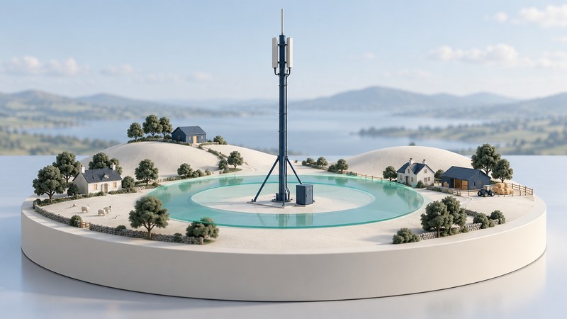
An omni cell aims to serve the area around a base station with an approximately omnidirectional horizontal antenna pattern. It can be attractive where users are sparse and demand is modest. The central design question is how to provide usable two-way coverage while carrying the traffic that arrives at busy times.
On a narrow screen, swipe tables sideways or focus them and use the arrow keys.
Compare omni and sectorized coverage
| Arrangement | How to picture it | Engineering consequence |
|---|---|---|
| Omni cell | One cell serving around the site in azimuth | A shared coverage area and its available radio resources serve demand around the site. |
| Sectorized site | Directional antennas serving separate angular regions | Traffic and interference can be managed by sector, with more antenna and radio planning. |
Omnidirectional describes the intended horizontal pattern. Height, vertical pattern, downtilt, terrain and buildings still influence the field strength at a user. A circular map symbol is therefore a planning shorthand. Sector boundaries are also approximate: real antenna patterns overlap and have sidelobes.
Separate three questions: can a user exchange signals with the site, can the radio resources admit the user’s traffic, and can the backhaul carry that traffic onward? Each can limit the service independently. Raising transmitted power addresses only part of the first question.
Place the RBS 1140 in the CDMA2000 era
Ericsson’s 2004 review of CDMA2000 Expander base stations (PDF) describes the RBS 1140 as a two-carrier omni-cell option for small to medium capacity and rural hot spots. The same discussion contrasts it with the smaller single-carrier RBS 1143 and larger macro base stations. This is the useful historical context: a family of configurations serving different coverage and capacity needs.
Read two carriers as a specific equipment configuration, with its associated processing, radio and spectrum requirements. It does not directly translate into two calls, twice the area or a universal data rate. Keep the radio generation and product variant attached to the specification. A modern cellular deployment needs its own architecture and equipment evidence.
Coverage has an uplink as well as a downlink
- User equipment → radio uplink → base station
- Base station → radio downlink → user equipment
- Base station ↔ backhaul ↔ network services
A handset may detect a base station yet fail to sustain a useful uplink. The two directions use different transmitters, power budgets and receive conditions. Evaluate the limiting direction using actual antennas, feeder losses, receiver requirements and interference assumptions.
A terrain profile also changes the question. A valley settlement behind a ridge can need a different site location or coverage arrangement from homes spread across flat farmland. More nominal coverage radius on paper provides little help if the actual route remains obstructed. Measurements and a documented propagation model are the way to test the assumption.
Work through a low-traffic rural example
Then ask whether the constrained resource is the radio sector, a shared backhaul link, power resilience or a service elsewhere in the network. Treat a coverage complaint and a congestion complaint as hypotheses to test, even when users describe both as a weak signal.
Make the site proposal reviewable
- Map: intended users, terrain, site elevations and candidate antenna locations.
- Demand: simultaneous use, service mix, busy periods and growth assumptions.
- Radio: exact technology, spectrum, carriers, antenna patterns and uplink/downlink budgets.
- Infrastructure: power, backhaul, access and maintenance constraints.
- Validation: field measurements and acceptance criteria at representative user locations.
The RBS 1140 story is valuable because it exposes a recurring design choice: match infrastructure to a place and its demand. Preserve that reasoning while keeping the historical equipment’s capabilities in their documented period.