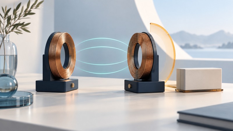
Magnetic induction communication transfers information through a changing magnetic field that couples one coil to another. The geometry matters: distance, orientation, coil shape and surrounding materials affect the signal available to the receiver. Understand that physical relationship separately from the protocol that identifies devices and protects their messages.
This is a conceptual guide for readers comparing short-range wireless techniques. It explains the questions to ask about a system; use the exact equipment documentation for construction, tuning or installation.
Follow the changing field
Current in a transmitting coil produces a magnetic field. When that field changes, it can induce a voltage in a nearby receiving coil. The transmitter encodes information through controlled changes, and the receiver interprets the resulting signal using the agreed communication method.
Texas Instruments' Antenna Reference Guide, particularly its induction and coupled-inductor appendices, illustrates this relationship for a historical low-frequency identification system. The principles explain coupling; the guide's old product ratings and regional limits apply to its documented equipment and period, not a new installation.
In a simple aligned-coil arrangement, moving the receiver farther away reduces coupling. Rotating or moving it sideways changes how the field crosses the receiving coil. A close receiver in an unfavorable orientation can therefore receive less useful signal than expected from distance alone.
Field-line drawings are models of direction and distribution. Their drawn edges do not form a physical wall. Real performance depends on field strength, receiver sensitivity, interference and the complete geometry.
Compare the physical link and the application
On a narrow screen, scroll the table sideways. Keyboard: focus the table and use the arrow keys.
| Question | Why it matters | Evidence to seek |
|---|---|---|
| What operating frequency and protocol are used? | Magnetic coupling supports different system designs | Exact device and protocol documentation |
| How are the coils positioned? | Orientation and offset change coupling | Tested operating positions and enclosure drawings |
| What materials surround them? | Nearby metal can alter fields and tuning | Results in the actual mounting environment |
| Is the receiver powered or energized by the field? | Energy transfer and data reception impose different requirements | Power architecture and specified operating conditions |
| How are peers and messages validated? | A received signal still needs an application trust decision | Authentication, integrity and access-control design |
For example, passive identification equipment may obtain operating energy from a reader's field, while an independently powered communications device has its own supply. Avoid transferring one system's range or energy claims to another simply because both use coils.
The early wireless-headset market also explored magnetic induction for communication close to a user. That is a different application from a passive tag, with different power, traffic and receiver requirements. The recurring design question is whether the chosen physical link fits the intended movement and information exchange.
Treat security as a complete interaction
Short operating distance can make deliberate placement convenient and limit ordinary communication reach. Confidentiality, authenticity and permission still depend on the implemented system. Ask which device is authenticated, which data is protected, and what action a received message is allowed to trigger.
NFC is a familiar example that uses magnetic coupling within a defined set of communication specifications. The NFC Forum's security overview describes protections across specifications, devices and applications, including authentication and access control. NFC is one application family, not a name for every magnetic-induction link.
The Forum's 2026 security roadmap also discusses relay-based threats. A relay forwards an interaction between separated endpoints, so physical proximity assumptions need their own treatment. A roadmap describes development direction; check the actual product's supported protections before relying on them.
Evaluate a proposed system realistically
Ask the supplier for tests covering the required distance, orientations, motion, enclosure and nearby materials. Use approved demonstration equipment to compare those conditions without changing its antenna, power or tuning beyond documented controls.
In a fictional evaluation, a tag reads consistently when held face-on to a reader but fails after being turned inside the intended holder. Record the holder, angle and repeated outcomes, then investigate the supported mounting arrangement. Describing the result as a universal “short range” limit would lose the information needed to resolve it.
Keep link establishment, data correctness and the resulting application action as separate acceptance checks. The RTLS standards guide explains similar interface-evidence questions for locating systems. A useful comparison identifies the exact technology, demonstrates the intended interaction and states the conditions under which it was tested.