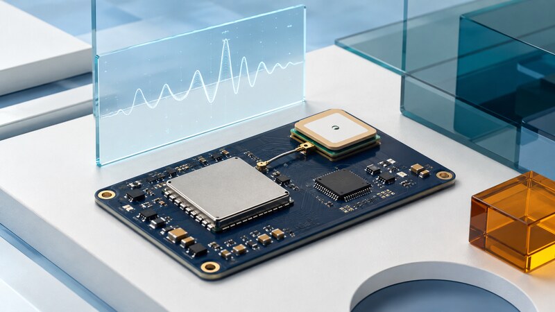
A GPS chipset supplies part of a satellite receiver's radio and signal-processing functions. A GNSS module packages more of the receiver into an integrable component. A development board adds connectors, power circuitry, and other conveniences for evaluation.
Choose at the level you can support. A smaller component may demand more RF design and validation work. A module can simplify integration, while still requiring an appropriate antenna, power supply, layout, host interface, and firmware configuration.
Compare complete operating requirements
| Requirement | What to inspect | Why a headline can mislead |
|---|---|---|
| Signals and bands | Exact constellations, frequency bands, and simultaneous modes. | Multi-band variants in one product family can differ. |
| Positioning method | Standalone, augmentation, RTK, and raw-observation support. | An RTK feature needs compatible reference data and conditions. |
| Acquisition | Cold, warm, hot, and assisted-start test definitions. | A hot-start figure does not describe an unprepared receiver. |
| Power | Acquisition, tracking, backup, and peak supply requirements. | A low tracking number does not describe the whole product. |
| Interfaces | Electrical levels, protocols, bandwidth, and timestamp fields. | A physical serial connection does not guarantee usable data. |
| Lifecycle | Exact order code, firmware support, documentation, and availability. | A family name alone does not specify the part to build around. |
For a documented example, u-blox's ZED-F9P product page lists variants with different signal-band combinations. Use the matching data sheet and integration documentation rather than assuming that every variant shares every capability.
Treat the antenna and power supply as part of the receiver
The antenna must support the intended bands and installation. Check the required ground plane, antenna orientation, cable loss, gain, and any active-antenna supply requirements. Keep the RF path consistent with the manufacturer's layout guidance and the board stack-up.
Digital clocks, switching regulators, displays, cables, and nearby transmitters can affect reception. Compare the bare evaluation setup with the assembled product while its other subsystems operate. An open-board demonstration does not validate the final enclosure.
The ZED-F9P-05B data sheet is an example of the electrical and performance detail to consult for a specific part. Its limits and test conditions apply to that part; they are not generic wiring instructions for another receiver.
Check supply startup and peak behavior, not only average current. A receiver that resets when another radio transmits can produce location gaps that look like a satellite problem.
Worked example: the serial link can be the bottleneck
A faster output stream does not guarantee a fresher fix. Preserve measurement timestamps and compare them with host receipt time. Use validity and solution-status fields rather than accepting every parsed coordinate.
In another deliberately simplified budget, a receiver drawing 25 mA for 10 seconds and 0.05 mA for the other 50 seconds averages about 4.21 mA over one minute. This excludes the host, antenna, regulator losses, startup behavior, and communications, and does not predict a real product's battery life.
Build the host interface around documented messages
Confirm protocol versions, field units, checksums, invalid-value handling, and configuration persistence. Some settings take effect immediately; others need a save or restart. Retain a known configuration and firmware identifier with every evaluation log.
On supported systems, gpsd provides a service and diagnostic tools for supported receivers, allowing applications to consume location data through a common interface. Check hardware compatibility and the documentation corresponding to the installed release.
AI-assisted coding is useful for parsers, log converters, and replay tools when the protocol reference is supplied. Test with valid records, truncated packets, bad checksums, invalid fixes, missing fields, and out-of-order timestamps. Do not let a generated parser turn an absent coordinate into a valid zero.
Raw carrier-phase observations, position messages, and correction messages are different data products. Preserve the one your downstream workflow actually needs.
Evaluate the assembled system in representative conditions
Measure time to a usable solution under clearly documented start conditions. Then test sustained tracking, recovery after obstruction, power interruption, and operation with the product's other electronics active. Repeat under comparable conditions and report the distribution of results.
For corrected positioning, record correction age, solution transitions, and reference metadata. For timing applications, evaluate the timing output and its validity behavior separately from the position display. Use reference equipment suitable for the quantity being tested.
Keep a concise evidence package: exact hardware and firmware, antenna and enclosure, configuration, test conditions, raw logs, and acceptance criteria. This makes a component comparison useful when the prototype becomes a product.