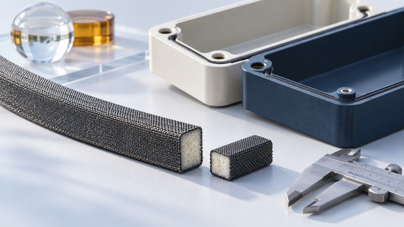
A conductive fabric gasket can help maintain an electrical contact path across an enclosure seam. Choose it as part of the complete joint: contact surfaces, gap tolerance, compression force, attachment, environment and the required electromagnetic test. A material's headline shielding figure is only one piece of that decision.
Understand the contact path
Fabric-over-foam gaskets combine a compliant core with a conductive outer fabric. Laird's fabric-over-foam product overview describes a range of profiles and materials. The selected shape must maintain the intended contact as the enclosure closes and tolerances vary.
Draw the electrical path through the mating parts and gasket. Identify the actual surfaces that meet, including plating, paint, adhesive and seams. Specify the intended conductive finish and its preparation through the enclosure design process. Arbitrarily removing coatings can change corrosion protection or other requirements.
On narrow screens, focus the table and use the arrow keys or swipe to see every column.
| Input | What to record | Why it matters |
|---|---|---|
| Gap | Minimum and maximum closed gap in millimeters | Determines the compression range |
| Mating surfaces | Material, finish and contact geometry | Defines the electrical and corrosion interfaces |
| Closure | Fasteners, spacing and available closing force | Controls local contact along the seam |
| Environment | Temperature, moisture and expected reopening | Guides material and durability qualification |
| Performance | Frequency range, test method and assembly target | Connects component evidence to the product requirement |
Calculate compression across the tolerance range
For a gasket with free height h and a closed gap g, nominal compression is (h − g) ÷ h × 100%. Use consistent units. Compare the resulting range with the exact part's specified working range and force-deflection data.
Illustrative 2 mm gasket
Assume a gasket free height of 2.0 mm and a closed gap of 1.4 mm. Compression is (2.0 − 1.4) ÷ 2.0 × 100 = 30%. If the gap varies from 1.2 to 1.6 mm, compression varies from 40% down to 20%. This example holds free height constant; a real tolerance analysis must include variation in gasket height too.
The example calculates fit; it does not establish that 20–40% is acceptable for a chosen material. Consult the part-specific document, such as Laird's EcoTemp 661 datasheet, for the conditions attached to that product's properties. Avoid transferring a recommended compression or temperature limit between unrelated profiles.
Evaluate corners, joints and locations between fasteners. A single centerline gap measurement can miss a locally open seam or an over-compressed section. Repeated opening also deserves attention when the enclosure will be serviced.
Qualify a sample in the intended assembly
- Document the candidate part, lot, free height, attachment method and mating finishes.
- Measure representative closed gaps and calculate compression at the extremes.
- Check that the enclosure closes with the intended fasteners and force, without unacceptable deformation.
- Inspect continuity of contact using the design's approved evaluation method, including corners and joins.
- Run the required assembly-level electromagnetic tests and retain the configuration and results.
A component test fixture and a finished enclosure present different geometries. Connectors, vents, cable penetrations and other seams remain part of the assembly. Interpret shielding data alongside its frequency range, fixture and compression condition; the gasket alone cannot establish the finished product's compliance.
Keep a reusable fit and test record
Use the gasket fit record to capture dimensions, tolerance assumptions and qualification results. If the enclosure finish, fastener spacing, supplier part or adhesive changes, use that record to decide which checks need repeating.
Define the gasket's job explicitly. An EMI contact requirement, an environmental seal and a thermal interface are different design requirements, even when one assembly needs all three. The heat-sink guide covers thermal contact and cooling decisions. For traceable equipment changes during evaluation, the cable-labeling guide helps maintain a reproducible setup.