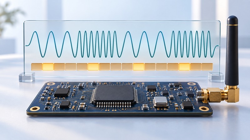
Frequency-shift keying carries information by changing a carrier’s frequency. In binary FSK, two frequency states represent the two symbol values. A working data link requires the transmitter and receiver to agree on modulation, rate, frequency settings and packet format, with enough receiver bandwidth for both the signal and frequency error.
On a narrow screen, swipe a table sideways or focus it and use the arrow keys.
Read the settings as a linked set
| Parameter | Meaning | Question to ask |
|---|---|---|
| Carrier frequency | Nominal center of the radio channel | Do both endpoints use the intended channel? |
| Frequency deviation | Offset of each binary-FSK tone from the center | Is the specification one-sided deviation or total tone separation? |
| Bit rate / symbol rate | Data bits or modulation symbols per second | Does coding change the relationship between payload bits and symbols? |
| Receiver bandwidth | Width of the receiver’s channel filter | Does it admit the wanted spectrum with frequency-error margin? |
| Packet format | Preamble, synchronization, length, coding and CRC conventions | Can the receiver recognize and validate the sender’s packets? |
Gaussian FSK shapes transitions to manage the transmitted spectrum. The shaping parameter and receiver implementation matter, so two devices described simply as “FSK” still need a compatible configuration. Payload throughput also includes packet overhead, turnaround time and any retries.
As a concrete reference, the Texas Instruments CC1101 datasheet (PDF) documents supported modulation formats, programmable rates, filtering and packet features. Read the test conditions alongside each sensitivity or current figure. Values measured at one rate and bandwidth are not a performance guarantee for another configuration.
Work out tone spacing before setting bandwidth
Keep units explicit. A kHz deviation and a kbit/s rate describe different quantities. Label every worksheet column with its unit, and distinguish the symbol rate from application payload rate.
Include both endpoints’ frequency error
A receiver tuned exactly to its programmed value can still be offset from the actual transmitted signal. Crystal tolerance, temperature, loading and aging contribute. TI’s CC11xx frequency-offset design note (PDF) explains how transmitter and receiver errors combine and affect filter selection.
A narrower filter can reject more unwanted energy while also clipping the desired signal if the assumptions are wrong. Frequency correction can reduce residual offset in a supported design, but its acquisition range and behavior must be checked.
Compare a complete operating point
For each candidate, record supply voltage, modulation, rate, deviation, bandwidth, transmit power, packet length and the error criterion used for sensitivity. Also record antenna and matching-network conditions. A headline sensitivity figure becomes meaningful when the other settings match your proposed use.
The CC1101 product page provides the datasheet, reference material and development resources. Use the manufacturer’s current tools and reference design as a starting point, then preserve the generated configuration with your test results.
Use the FSK link worksheet (plain text) to keep endpoint settings and units aligned. It includes the calculation above and blank fields for measured results.
Test packet delivery, not only received strength
- Begin with a documented compatible configuration and an appropriate controlled test arrangement. Verify both endpoints’ frequency and packet settings.
- Send a known number of identifiable test packets. Count valid received packets, duplicates and failures using a stated rule.
- Record RSSI where available, but judge the link using successful decoding as well as signal level.
- Change one parameter or condition at a time, preserving the original working configuration.
- Repeat relevant tests over supply, temperature, antenna orientation and realistic interference conditions within the equipment’s supported limits.
If 980 of 1,000 distinct test packets arrive valid on the first attempt, the observed first-attempt packet loss is 20 / 1,000 = 2%. State whether retries were enabled and whether the counter measures attempts or application messages. Those definitions can change the reported result.
Any over-the-air transmission needs a configuration and operating conditions permitted in its jurisdiction. A chip’s tuning range alone establishes hardware capability. Use applicable radio requirements and manufacturer compliance guidance for the intended product or test.