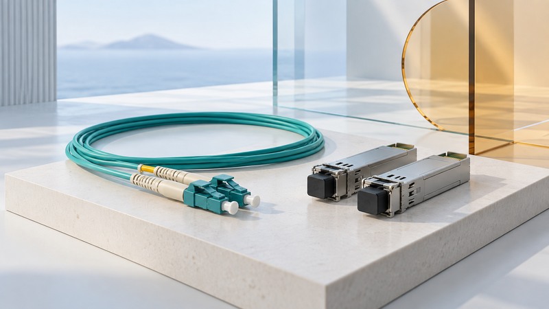
A fiber-optic network link works as a complete matched system: equipment ports, supported transceivers, optical specifications, cable and connectors. Begin with the two endpoints and the installed cable record. A connector that fits is only one part of compatibility.
Build an end-to-end link record
Record the equipment model, port type and software support at both ends. Then identify the transceiver part numbers, Ethernet standard and rate, fiber type, connector arrangement and path length. Include patch panels, intermediate connections and splices in the path—not just the visible patch cord.
On narrow screens, focus the table and use the arrow keys or swipe to see every column.
| Item | What must agree | Common mistaken shortcut |
|---|---|---|
| Equipment support | Host port, rate, transceiver type and supported software | Every module of the same physical size will work |
| Optical standard | Compatible transmit/receive characteristics at both ends | Any pair of optics labeled “10G” will communicate |
| Fiber and reach | Single-mode or specified multimode grade, length and loss | Cable jacket color establishes its complete specification |
| Connectors and path | Connector type, polish, fiber count and correct polarity | Matching connector shells prove a compatible link |
Use labels and installation records to identify the cable. If those are missing, have the path identified and tested rather than selecting optics by appearance. The cable-labeling guide provides a simple endpoint inventory approach.
Compare a specific optical pair
Cisco's 10GBASE SFP+ module data sheet distinguishes 10GBASE-SR optics for multimode fiber around 850 nm from 10GBASE-LR optics for single-mode fiber around 1310 nm. It also lists reach and optical power limits for particular modules. Use the exact row, fiber grade and equipment compatibility information for the parts under consideration.
Worked compatibility decision: suppose a building record identifies a duplex multimode path, and both switches support the proposed 10GBASE-SR modules. That establishes a candidate combination. You still need to confirm the cable grade, total length, connector arrangement, polarity and measured loss. Substituting an LR module at one end because it has the same LC connector would break the intended optical pairing.
Some single-fiber bidirectional systems use complementary wavelengths. Those need their specified paired modules; they are not simply two arbitrary identical transceivers. Keep the manufacturer's pairing instructions with the link record.
Understand the link-budget calculation
Optical power is commonly specified in dBm; losses are expressed in dB. To estimate the weakest received signal, subtract the path's worst-case loss from the transmitter's minimum output. Compare the result with the receiver's required minimum, using the applicable vendor specifications and engineering allowances.
Invented teaching example: minimum transmit power of −5 dBm minus 4 dB of total path loss gives −9 dBm at the receiver. If the receiver needs at least −13 dBm, the calculated margin is 4 dB before additional design allowances. These figures do not describe a particular product or authorize an installation.
Also check the strongest possible received signal against the receiver's maximum input. A weak-signal calculation alone cannot identify overload. Dispersion, specified reach and equipment compatibility impose other limits; satisfying one power calculation does not establish that a link is supported.
Handle and troubleshoot the path safely
Never look into a fiber or optical port. Cisco's fiber inspection and cleaning guidance describes precautions and inspection methods. Have trained personnel use the appropriate equipment and approved process, including disabling optical sources before inspection as directed. Dust caps help protect disconnected parts, but do not prove a connector is clean.
- Check the link record against the installed modules and switch configuration. Confirm both ports are enabled and support the intended rate.
- Review interface status, error counters and optical diagnostics where supported. Compare readings with the exact module's limits.
- Have the documented fiber path, polarity and connector condition checked. Do not improvise with household cleaners or touch fiber end faces.
- Change one known-compatible element at a time and record the result. Restore the intended arrangement and verify traffic and error counters afterward.
Keep bends within the cable manufacturer's limits and protect exposed connectors. Save final module identifiers, test results and endpoint labels so a future repair starts from evidence.