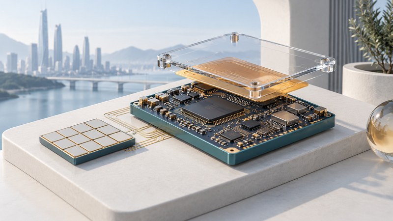
An efficient millimeter-wave radio depends on the antenna, amplifier, package, beamforming electronics and operating workload. Start by identifying the boundary of an efficiency claim, then compare designs under the same output, data rate and measurement conditions.
Keep the efficiency measures separate
| Measure | Meaning | Boundary to check |
|---|---|---|
| Antenna radiation efficiency | Radiated power relative to power accepted by the antenna | Mismatch may be treated separately; ask exactly what the reported figure includes. |
| Power-amplifier efficiency | Useful RF output relative to DC input for the stated metric | Drain efficiency and power-added efficiency have different definitions. Record bias, waveform and output backoff. |
| Total radio power | Power consumed by the chosen radio-system boundary | Include or explicitly exclude converters, clocks, beamforming, control and cooling. |
| Energy per delivered bit | Energy divided by successfully delivered useful data | Specify rate, load, retransmissions, idle time and whether the measurement includes one or both endpoints. |
A percentage without its definition can be misleading. A high antenna efficiency may coexist with substantial circuit power. A very fast radio may use more watts yet fewer joules per delivered bit under one workload. Compare like-for-like boundaries before drawing a system conclusion.
Locate losses along the RF path
- RF generation and conversion
- Amplification and beam control
- Package and feed network
- Antenna / array → radiated field
This functional sequence omits implementation-specific ordering and shared blocks. Loss, mismatch, bias power and thermal behavior can affect different stages.
Energy efficiency in a mmWave antenna system is not only the efficiency of the antenna. It includes the power amplifier, impedance matching, beamforming network, power combining, data converters, local oscillators, control circuits, calibration, and heat removal. A design that performs well in simulation can lose efficiency if the package adds parasitics, if the board material absorbs energy, or if heat shifts the behavior of the front end.
Antenna-electronics co-design treats those interactions as part of the design problem from the beginning. The antenna can help combine power. The package can reduce feed loss. The beamformer can be laid out around thermal and electromagnetic constraints. The power amplifier can be optimized for the antenna load it will actually see. The result is a radio that behaves as a single physical system instead of a chain of separately optimized parts.
Receive circuits, calibration and digital processing add their own costs. An array can improve directional gain while increasing the number of active RF chains or control components. The useful comparison is the resulting link and energy behavior for the intended duty cycle.
Compare integration choices
| Approach | Potential advantage | Tradeoff to investigate |
|---|---|---|
| On-chip antenna | Very close circuit/antenna integration | Substrate loss, area, radiation behavior and process constraints. |
| Antenna in package | Short interconnect with packaging/material flexibility | Package stack-up, tolerances, feed loss, thermal path and manufacturing yield. |
| Integrated module | A tested assembly of antenna and RF functions | Mechanical integration, calibration, shielding, cost and supplier support. |
IBM’s antenna-in-package and module integration publication discusses the role of package integration in millimeter-wave communications. The engineering choice depends on frequency, materials, antenna aperture, bandwidth, polarization, enclosure and production constraints. “On chip” identifies placement; it does not establish the best efficiency for every design.
There are several ways to integrate antennas with mmWave electronics. An on-chip antenna places the radiating structure on the same silicon or semiconductor platform as the circuits. Antenna-in-package places the antenna in the package around the RF chip, often using laminate, fan-out wafer-level packaging, ceramic, glass, or other high-frequency materials. Module designs combine antennas, beamforming chips, power management, shielding, and thermal structures into a compact unit.
On-chip antennas can be extremely compact and closely coupled to electronics, but silicon substrates can introduce loss. Antenna-in-package approaches often offer better radiation efficiency and more flexible materials while keeping the path between chip and antenna short. In commercial mmWave systems, package and module integration have become especially important because they balance size, performance, cost, manufacturability, and thermal behavior.
Read the Georgia Tech result in context
Georgia Tech’s July 4, 2018 research release describes antenna-electronics co-design for millimeter-wave transmitters, including antenna-based outphasing. The work aimed to maintain useful efficiency at both peak and average operating power for modulated signals. The institution’s release establishes the 2018 context even where later migrated web pages carry newer path dates.
The broader lesson is joint optimization: antenna behavior and circuitry can be designed together rather than treated as independent blocks. To compare a prototype with a product, look for the waveform, frequency, bandwidth, output power, error-vector magnitude, spectral behavior, package and thermal conditions. A proof of concept supplies evidence for the measured configuration, not guaranteed battery life in a handset.
Calculate energy per useful bit
The figures are invented arithmetic, not measurements or product claims. A useful experiment would measure the same system boundary, delivery criterion, channel conditions and workload, including the time spent waiting or retransmitting. Battery life also depends on the rest of the device.
Ask what was demonstrated
- Is the result simulated, a measured component, a packaged prototype or a complete operating link?
- Which efficiency definition and operating point were used?
- What happens away from peak output, with the intended modulation and temperature?
- How are beam scan angle, enclosure blockage and calibration treated?
- Does the comparison include the same data rate, error performance and power boundary?
Millimeter-wave hardware also appears in radar, sensing and research beyond current mobile products. Those applications may share integration challenges while using different waveforms, bands and acceptance criteria. Label research separately from deployed 5G capabilities and avoid transferring one demonstration’s savings to another system.