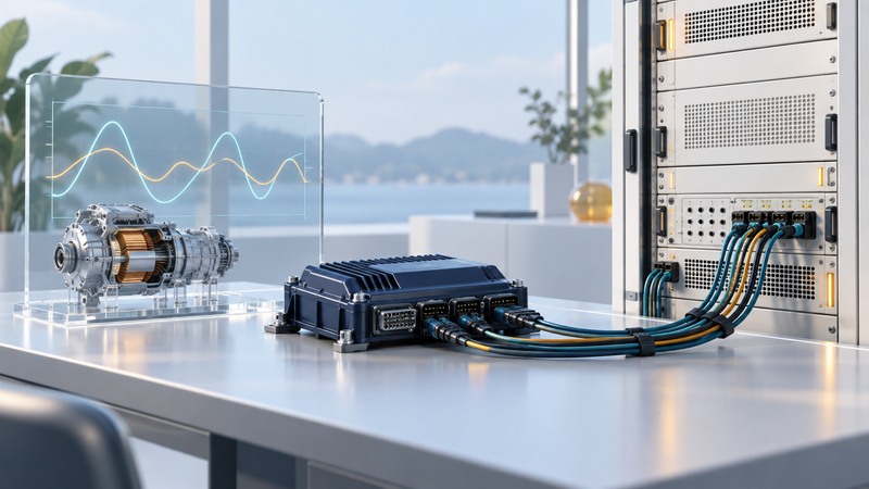
Hardware-in-the-loop (HIL) testing connects a real controller to a real-time model of the equipment it controls. For a hybrid or electric powertrain, that model can represent the inverter, motor, battery and mechanical load. The useful result is evidence that a specified controller function behaves correctly under defined conditions.
Begin with one requirement, the controller software version, a reference model and the available signal interfaces. This guide covers controller HIL, where signals represent the power plant. Power HIL includes real power exchange and requires a different test arrangement and engineering review.
Choose the plant boundary to answer the question
For a motor-current controller, define where gate commands leave the controller and where current, voltage, speed and position signals return. List modeled dynamics and deliberate simplifications. An averaged inverter model may support supervisory or speed-control work; tests of switching edges and dead time need a representation that resolves those events.
The technical paper The What, Where and Why of Real-Time Simulation discusses the tradeoff between timestep and model accuracy, including motor-drive validation against physical measurements. Use a reference appropriate to the behavior being tested.
Before closing the loop, compare steady operating points and representative transients with an independently trusted model or measurements. Record error tolerances and operating ranges. A model validated at one speed and torque leaves other conditions open.
Budget the complete signal loop
On a narrow screen, scroll the table sideways. Keyboard users can focus the table region and use the arrow keys.
| Quantity | Meaning | Check |
|---|---|---|
| Simulation timestep | Interval at which the numerical state is advanced | Worst-case execution finishes within the required step |
| Event capture resolution | How precisely an input transition is recorded | PWM and encoder timing meet the test requirement |
| End-to-end latency | Delay through input, computation and output | Measure the complete path and its variation |
| Model accuracy | Agreement with the relevant physical behavior | Compare outputs with a reference across the test range |
Fictional timing screen
A 10 kHz PWM signal has a 100 microsecond period. A 5 microsecond model step provides 20 steps per period. If a nominal 5 microsecond task requires 6 microseconds in a worst-case run, it misses its deadline.
Twenty steps per period alone establishes neither ripple accuracy nor dead-time fidelity. A 1 microsecond event still needs suitable capture and solver treatment. Change the model, solver or execution arrangement, then repeat both the deadline check and reference comparison.
OPAL-RT's motor-drive HIL preparation guidance treats model fidelity, I/O and loop timing together. This is a useful way to organize a bench specification; advertised processor speed supplies only part of the evidence.
Make a signal map before interpreting faults
For every channel, record signal direction, units, range, polarity, offset, electrical interface, update rate and calibration method. Check how invalid values and disconnections appear to the controller. A scaled current signal with the wrong sign can create a convincing-looking control fault.
- Verify channel identity and scaling against a known value with the approved bench procedure.
- Check timestamp alignment and the actual acquisition rate.
- Run a stable operating point and compare commanded and measured quantities.
- Introduce one modeled disturbance and inspect the expected response.
When results look wrong, first inspect units, sign, clipping, latency, timestep overruns and initial state. Then investigate controller logic and plant assumptions. Preserve the failing configuration so a later correction can be demonstrated.
Write scenarios with observable pass criteria
A scenario needs an initial state, a stimulus, expected behavior, measurable limits and a reset condition. Include normal startup, command changes and representative faults within the validated model's scope. Set limits from the actual requirement and controller design.
On a narrow screen, scroll the table sideways. Keyboard users can focus the table region and use the arrow keys.
| Scenario | Stimulus | Evidence |
|---|---|---|
| Torque request change | A defined command step at a specified speed | Tracking error, settling time and current limit behavior |
| Supply disturbance | A modeled DC-link sag with stated depth and duration | Control state, protection timing and recovery |
| Sensor fault | A defined dropout or implausible signal | Diagnostic response and the required safe state |
| Restart | Restoration after a specified fault | Allowed restart sequence and retained diagnostic record |
Archive the controller build, model version, parameters, simulator configuration, input trace and results together. Record acceptance, failure or an unresolved model limitation for each requirement. Passing HIL supports the tested behavior within that boundary; physical validation and system-level approval remain separate evidence.
For the energy-management context behind the controller, see hybrid-electric bus operation. Chip supply-noise modeling belongs to the separate power-integrity simulation guide.
Powertrain HIL test brief
Powertrain HIL test brief — plain-text download. Save a copy and fill it in with your own information. The file includes instructions, assumptions and references so it can be used independently.