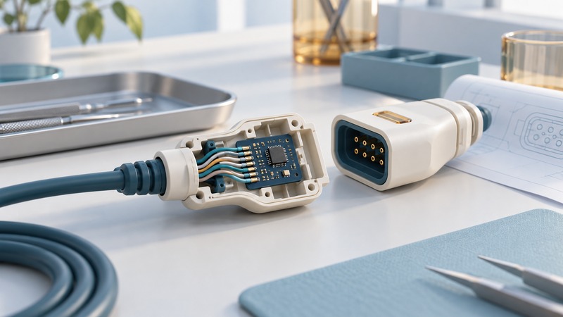
A smart medical cable needs a specification for both the connection and the information it exchanges with the device. Define the intended use, mechanical loads, electrical signals, identification behavior and failure response before reviewing supplier samples.
This guide is for OEM engineering and supplier discussions. Acceptance criteria come from the complete device’s requirements and risk analysis. A connector’s feature list supplies inputs to that work; system validation determines whether the assembled device performs as intended.
Define what “smart” must accomplish
A historical example is MEDCONX’s intelligent connector assembly patent, filed in 2004 and published as a granted patent in 2009. It describes an integrated circuit block and housing-alignment features for a cable interface. The document records a design concept and its claimed construction. Product availability, manufacturing capability and performance require separate evidence.
For your design, write the data contract: accessory type, revision, serial or lot information, calibration fields if used, and which values the device may update. Define how the host handles missing, corrupt or inconsistent information. Separate simple identification from any authentication requirement so the supplier knows what must be demonstrated.
If a disposable accessory includes a use limiter, specify the event that changes its state and the required behavior after an interrupted operation. Keep that behavior aligned with intended use and labeling. This is a design-verification question for the OEM; bypassing the limiter defeats the defined interface.
Specify the assembly, including its ends
On a narrow screen, scroll the table horizontally. Keyboard users can focus the table region and use the arrow keys.
| Area | What to define | Evidence to request |
|---|---|---|
| Conductors | Wire construction, signals, lengths and termination method | Drawings, process controls and continuity results |
| Mechanical | Mating orientation, retention, strain relief and flex conditions | Test method, fixture, loads and sample results |
| Electrical | Contact behavior, shielding and applicable device-derived limits | Measurements on the relevant assembly configuration |
| Embedded data | Field format, protocol, revision and invalid-data response | Interface specification and fault-injection results |
| Materials/processes | Use environment and any specified processing exposure | Traceability and evidence for the exact materials/process |
| Production changes | Permitted substitutions and notification requirements | Change agreement, lot identification and retest plan |
Fine wires make the termination region especially important to describe. Request sections or inspection evidence showing where conductors are supported, how insulation is removed and how the transition into the cable is controlled. Evaluate samples made by the intended production process. A carefully hand-built prototype may conceal an assembly problem.
Molex’s medical-technology overview describes custom interconnect and cable-assembly capabilities. Such a capability statement helps identify questions for a supplier. Obtain drawings, material declarations and applicable test evidence for the quoted assembly before accepting it.
Review failure behavior with the complete device
Include incorrect mating attempts, incomplete engagement, cable movement, an unreadable ID and an unsupported accessory revision in the engineering review where relevant. For each case, name the expected device response and the evidence needed to verify it. Use only device-specific approved test methods and limits.
For US medical-device development, FDA’s human-factors and usability-engineering guidance addresses intended users, uses and environments and reducing use errors. Apply that perspective to orientation cues, connection feedback and messages. Review the current guidance and the applicable device pathway with the responsible specialists; this worksheet does not determine regulatory compliance.
Make the supplier review actionable
- Send a controlled drawing and requirements matrix, with each criterion tied to its device-level purpose. Mark unresolved limits explicitly.
- Ask the supplier to identify what its standard offering covers and where custom development or additional evidence is required.
- Agree on representative samples, test configuration, acceptance limits and how results will be reported. Include connector electronics and host firmware versions.
- Review deviations with the device team. Record the effect on performance, usability and validation before accepting a substitution.
- Retain lot traceability, approved revisions and the change-notification agreement with the release package.
Specify cleaning, sterilization or environmental exposure only from the intended device process and supporting validation plan. The useful purchasing outcome is an agreed assembly and evidence package, with remaining device-level work assigned to an owner.
Keep a working record
Download the connectors worksheet (editable text). Save a copy, fill in the fields for your situation and record exceptions as well as successful checks. The worksheet includes its purpose, source links and any example assumptions.