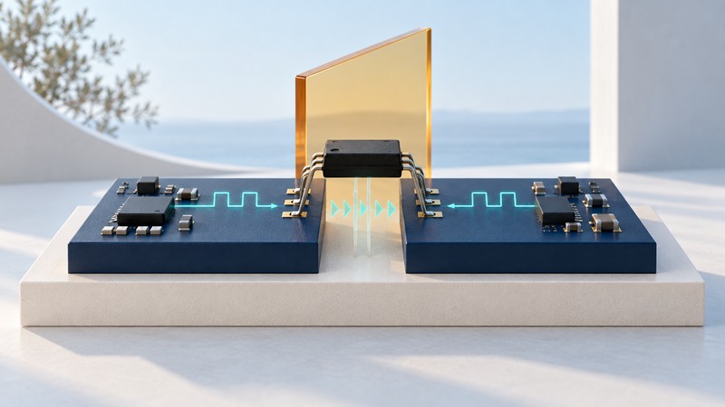
Digital isolation transfers logic information between circuits with separate electrical references. The isolator may couple the information magnetically, capacitively or optically. Start by drawing the two domains and every connection between them, then identify the electrical and timing requirements of that boundary.
This is a design-reading and selection guide. A component’s ratings are inputs to system design; a shock-protection barrier also depends on the applicable product standard, layout, power supply, connectors, installation and verification. Have the responsible safety engineer establish those requirements before choosing a part.
Draw the complete boundary
Name each ground and supply, and place the processor, sensor, communications connector and power converter on the correct side. Count forward and reverse signals. An SPI peripheral commonly needs clock, select and outbound data in one direction and returned data in the other; the actual interface may add interrupts or multiple selects.
Then look for alternate connections: programmer grounds, cable shields, oscilloscope grounds, USB, mounting hardware and an unisolated supply return. Each can change the intended separation. Decide how the assembled system will be debugged without accidentally creating a conductive path across the barrier.
Signal isolation and isolated power are separate functions. Some devices integrate both; others need a supply on each side. Record startup order, current budget and the return reference for each supply. Texas Instruments’ Digital Isolator Design Guide provides a useful reference for interfaces, supply considerations and implementation.
Read each rating as a different question
On a narrow screen, scroll the table horizontally. Keyboard users can focus the table region and use the arrow keys.
| Specification | Meaning for selection | Record with the value |
|---|---|---|
| Working voltage | The permitted continuous stress across the barrier over the specified operating life. | RMS/DC or repetitive-peak definition, lifetime assumptions and exact package. |
| Withstand voltage | A defined dielectric test stress for a specified duration. | Test standard, waveform, duration and certificate scope. |
| Surge rating | Response to a defined high-voltage transient test. | Pulse definition and the insulation requirement it supports. |
| Creepage / clearance | Distance along an insulating surface / through air. | Package, board geometry, pollution/material/altitude assumptions and product standard. |
| CMTI | Tolerance of rapid common-mode voltage change between the two references while preserving specified operation. | Minimum rating in kV/µs and the stated test conditions. |
TI’s isolator selection brief distinguishes these quantities. Keep them in separate worksheet fields: the largest voltage printed on a product page is often a test rating, while day-to-day operation is governed by a different specification.
Select the insulation function the system requires: functional isolation serves circuit operation, while basic or reinforced insulation addresses defined protection requirements. Verify the exact order code, package and applicable approvals in the current data sheet and certificates. Certification status can differ across variants.
Budget logic behavior and timing
Check input thresholds, output levels, supply ranges, channel directions and default outputs. A receiver expecting a defined inactive state needs that state when the transmitter loses power, when inputs float and during startup. Active-low control lines deserve particular attention: a default low can have a different meaning from “inactive.”
For a clocked interface, data rate alone is insufficient. Outbound clock delay, peripheral response delay, return-channel delay and processor setup time all consume time. Use maximum values over the relevant voltage and temperature ranges, including skew and pulse-width distortion. The operating mode determines which clock edge launches and captures data.
For an example of separately published parameters, TI’s ISO6463 product information lists propagation delay, channel directions, supply conditions and default-output variants. Follow the associated data sheet for the exact timing limits rather than transferring a family headline into your budget.
Compare technologies at the same operating point
Optocouplers, magnetic isolators and capacitive isolators each include device families with different speed, power, temperature and lifetime behavior. Compare selected parts under the same load, supply and switching conditions. A broad technology label is a poor substitute for measured or guaranteed specifications.
For optocouplers, include input LED drive and relevant aging/current-transfer behavior. For digital isolators, include both sides’ consumption and any isolated power converter. The converter’s emissions, efficiency and layout requirements can matter as much as the signal channel. Keep typical curves separate from guaranteed limits.
Ask suppliers to resolve missing conditions in writing. A spreadsheet or AI extraction can organize candidate specifications, but every consequential value should retain its data-sheet section, units and min/typ/max status.
Verify the assembled interface in stages
- Review the boundary drawing and exact pinout before powering an evaluation setup. Use the manufacturer’s recommended circuit and supply sequence.
- Verify logic levels and communication under documented low-voltage bench conditions before introducing the final environment.
- Exercise startup order, missing-side power, reset, idle and active states; observe actual outputs as well as decoded messages.
- Test the required clock/data patterns and operating corners, recording hardware revision, firmware, supply, temperature and measurement setup.
- Have qualified facilities perform any required high-voltage, surge, insulation and compliance verification to the applicable procedure.
A packet log can show communications failures, while a suitable timing measurement can locate their cause. Preserve both with the requirements worksheet. A bench exchange of valid bytes establishes only the conditions tested.
Keep a working record
Download the digital isolation worksheet (editable text). Save a copy for each comparison or test. It includes the example assumptions, fields for source references and space for your results.