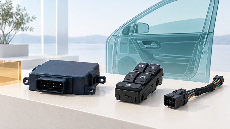
LIN connects small control functions through a scheduled serial network. Understanding a node requires following both the messages and the power path: firmware, controller interface, transceiver, voltage regulator and the load each have a role. Start with an exact schematic and device documentation, then investigate one layer at a time.
This guide is for learning and controlled bench development using documented hardware. Vehicle systems require manufacturer procedures and appropriate expertise; a working bench exchange does not validate an installation or a safety-related function.
Separate the jobs inside a node
On a narrow screen, scroll the table horizontally. Keyboard users can focus the table region and use the arrow keys.
| Block | Job | Question to resolve |
|---|---|---|
| Application firmware | Turns a signal or command into behavior. | What data, units, timeout and output state does the function require? |
| LIN controller/UART and software | Creates or receives the required frame fields. | Which frame identifiers, lengths, checksums and schedule apply? |
| Transceiver | Translates logic-side signaling to the physical LIN bus. | What supply, enable state and electrical interface does this part require? |
| Regulator and supervision | Power and reset behavior for the electronics. | Which rails remain powered in each mode, and how is reset released? |
| Load interface | Drives or reads the actual switch, sensor or actuator. | What independent limits and fault behavior belong to the load? |
A system basis chip, or SBC, integrates some of these interface and power functions. TI’s SBC overview describes this integration. Read the selected part’s block diagram to determine what remains external, including the application’s protocol logic and load driver.
Read the frame and the schedule together
The commander initiates frames with a header; the configured publisher supplies the response, which may be the commander node’s own responder task or another node. Older documents often use master/slave terminology. The identifier defines the frame, so interpret it through the network description instead of treating it as a simple device address.
Microchip’s LIN controller documentation identifies the break, delimiter, synchronization, protected identifier, data and checksum fields. Its register details apply to that controller. Use the exact device PDF and network definition when configuring your own hardware.
For diagnosis, record the schedule slot, expected publisher, frame length, checksum convention and the meaning of each signal. A decoder displaying bytes establishes only part of the chain. Check that the intended receiver updates its application value and handles a missing or stale frame as specified.
Use the actual device state diagram
State names are device-specific. For example, TI’s TLIN1028-Q1 datasheet, revision B describes normal, standby and sleep modes. In its normal mode the LIN transceiver and regulator operate; in standby the regulator remains on while normal transmission is disabled; in sleep the regulator is off and designated wake detection remains available. The state diagram and timing conditions determine the transitions.
Map each state to observable signals: supply rail, enable, reset, receive indication and bus activity. Include the microcontroller’s state and other loads in the same record. A low-current transceiver cannot compensate for an application processor or indicator that remains awake.
The same datasheet distinguishes recommended operation, absolute maximum ratings and fault behavior. Keep these separate when choosing a supply or fixture. A fault-tolerance number is not an instruction to operate continuously at that level.
Estimate current for the whole cycle
Measure at the boundary you intend to budget. Current into one low-voltage rail and current drawn from the upstream battery are different quantities when regulation and other circuitry intervene. Preserve the voltage, measurement bandwidth and averaging interval.
Investigate a controlled bench setup
- Use the documented evaluation-board or product bench arrangement, specified supply limits and suitable probes. Verify connections before energizing.
- Establish the expected power and reset sequence with the bus inactive. Compare the observed rails and enable states with the manual.
- Introduce the known frame schedule and observe logic-side signals, bus activity and decoded fields at defined points.
- Check application behavior and timeout handling using planned test cases that do not command uncontrolled motion.
- Enter the documented low-power state, apply a valid wake event and record the return to useful communication.
- Repeat after the intended restart conditions and retain traces, firmware identity and measured current.
If a frame appears on TXD but not on the bus, inspect the transceiver’s supply and mode. If the bus frame is present but the application never changes, inspect receive decoding, identifier mapping and firmware state. A bus that remains dominant requires diagnosis against the hardware’s protection and wiring documentation; repeated resets conceal the evidence.
End with a state table containing expected and observed behavior. It should explain both normal operation and the specific failure that the test was intended to expose.
Keep a working record
Download the automotive lin electronics worksheet (editable text). Save a copy for each comparison or test. It includes the example assumptions, fields for source references and space for your results.