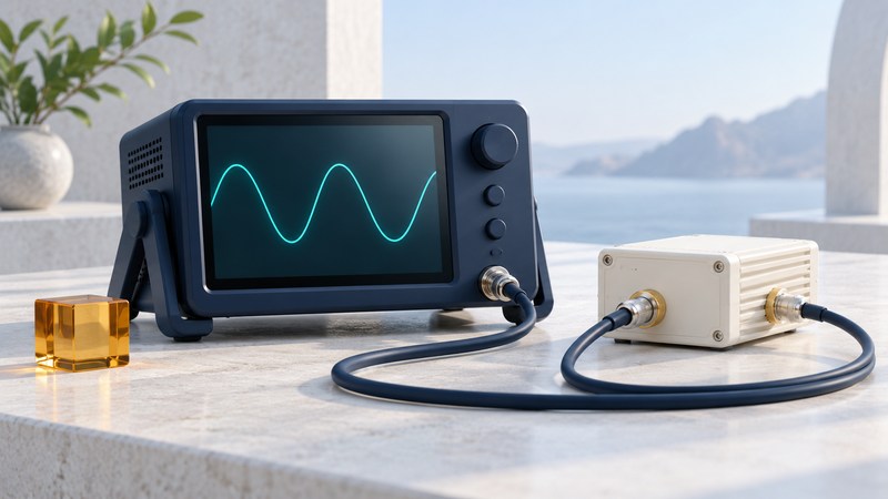
An audio analyzer examines a baseband signal: the electrical audio before transmission or after demodulation. A modulation analyzer examines how a radio-frequency carrier is varied to carry that information. Start with the question you need to answer, then choose the measurement and record the conditions that make the result meaningful.
On a narrow screen, swipe tables sideways or focus them and use the arrow keys.
Match the measurement to the question
| Question | Measurement | Interpretation |
|---|---|---|
| How far does an FM carrier move? | Frequency deviation, in Hz or kHz | Specify peak or RMS deviation and the modulation test signal. |
| How strongly is an AM carrier modulated? | Modulation depth, in percent | Interpret the envelope under the stated waveform and measurement method. |
| How much unwanted content accompanies a test tone? | SINAD, in dB | Signal plus noise plus distortion relative to noise plus distortion, within stated filters. |
| How much harmonic distortion is present? | THD, in percent or dB | Harmonics relative to the fundamental; bandwidth and included harmonics matter. |
| Does the audio path favor some frequencies? | Frequency response, relative dB versus Hz | Compare output over frequency with input level and reference frequency held consistent. |
Keysight’s AM/FM measurement documentation shows how a contemporary instrument reports demodulated waveform, deviation or depth, SINAD and THD. Available functions depend on the instrument and its options. A spectrum display helps locate carriers and unwanted emissions; a demodulation measurement answers a different question about the information carried by a selected signal.
Keep the RF and audio paths distinct
- RF sample → RF input within documented limits → carrier selection and demodulation
- Audio output → compatible audio input and load → level, response and distortion measurements
An RF connector, a speaker output and a line output can have very different signal levels and impedances. Before connecting equipment, establish the maximum possible output and the analyzer’s permitted input, DC limits and required impedance from their manuals. Use the documented coupler, attenuator or load arrangement for the exact equipment; the illustration above is a functional map.
Record where the sample was taken. A clean source tone can become distorted in a transmitter audio stage, a receiver, an overloaded analyzer input or an output amplifier. A result from the complete path cannot by itself identify which stage caused it. Comparing accessible stages under controlled conditions helps isolate the cause.
Read a result as a complete sentence
Now suppose a second report gives a better SINAD but uses a narrower audio filter. The changed filter can exclude more noise, so the numerical improvement needs to be evaluated under matching conditions. Record the filter, detector, averaging, test tone, output load and input level before comparing results.
The Keysight measuring-receiver guide (PDF) documents measurement-specific settings and procedures. Follow the manual for the instrument actually in use; menu names and supported ranges vary.
Build a repeatable measurement record
- State the question and acceptance criterion before measuring. Obtain the criterion from the applicable design specification or test procedure.
- Record equipment models, options, firmware, calibration status, connection point, adapters and relevant limits.
- Set and record stimulus frequency, level and modulation; confirm that the measurement input remains within its supported range.
- Record bandwidth, filtering, detector and averaging settings with the result and units.
- Repeat the measurement. If it changes unexpectedly, check connections, gain, overload indications and source stability before assigning the change to the device.
- Change one condition at a time and retain the original record.
The plain-text measurement record includes these fields and the worked example. It is intended for notes beside the equipment; it supplies no universal pass/fail threshold.
For a weak received signal, degraded audio may originate in the radio path even when the audio amplifier is healthy. For a strong signal, overload can produce distortion. Those are different hypotheses: vary a documented input condition and look for a repeatable response. A single attractive number is most useful when another person can reproduce it.